Deck
This handout is a compilation of some of the standard requirements based on the State Building Code and City Ordinance for projects of this type. This information packet does not contain all the specific codes for construction and should only be used as a guide. The permittee is responsible to meet all code requirements applicable to each project.
Note: If home is a Heritage Preservation Site prior approval from city planner and/or HPC is required before issuance of permit.
Submittals
- Deck permit application
- Site survey/site plan-scaled drawing accurately showing the location of the proposed deck with distances from property lines, utility easements, power lines and other structures.
- Deck plan drawing with dimensions and proposed materials to include the following information:
-
- Deck Plan Worksheet (attached)
- Existing house floor system
- Ledger board size and attachment metho
- Type of footing (see pg. 3 for alternative footing requirements.)
- Stairway location with dimensions and stringer size/spacing.
- Post size and spacing
- Dimensions of the deck
- Beam size
- Joist size and spacing
- Size and type of decking material. For composite decking, provide current code compliance research report (CCRR)
- Elevation drawing showing height above grade
- Owner-contractor waiver if homeowner is completing the work themselves
Required inspections
- Footings: Must be inspected and approved BEFORE any placement of concrete. (Helical and Diamond Piers will be inspected at framing or final.)
- Framing: Separate framing inspection is required for decks under 60” (5 feet) above grade.
- Final: A final inspection must be completed before the deck can be used. All stairways, handrails and guardrails must be completed before the final inspection will be approved.
Typical code requirements for residential decks
Footings: Are required for all decks attached to a structure with frost footings. Footings shall be a minimum of 42 inches deep and 14 inches across the bottom. Alternative footing types, pin piers and helical piers may be proposed.
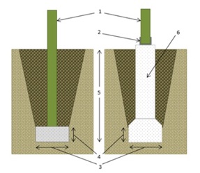
1. Columns shall be approved pressure preservative treated wood suitable for ground contact.
2. Manufactured post base required
3. Diameter of footing based on deck load (14” min.)
4. Minimum thickness of footings is based off table R507.3.1.
5. Footings shall be poured on dry, undisturbed soil a minimum of 42” below grade.
6.Cardboard forms shall be held up to allow for bell/flare thickness and diameter. 14” base minimum recommended for 6x6 posts.
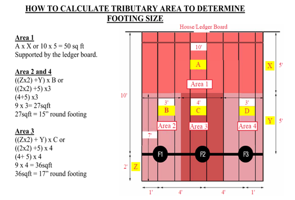
TABLE R507.3.1 MINIMUM FOOTING SIZE FOR DECKS
|
Live Loadb (psf) |
Tributary Area (sq.ft.) | Load Bearing Value of Soilsa,c,d (psf) | ||
| 1500e | ||||
| Side of a square footing (inches) | Diameter of a round footing (inches) | Thickness (inches) | ||
| 40 | 20 | 12 | 14 | 6 |
| 40 | 14 | 16 | 6 | |
| 60 | 17 | 19 | 6 | |
| 80 | 20 | 22 | 7 | |
| 100 | 22 | 25 | 8 | |
| 120 | 24 | 27 | 9 | |
| 140 | 26 | 29 | 10 | |
| 160 | 28 | 31 | 11 | |
- Interpolation permitted; extrapolation not permitted
- Live load= 40 psf, Dead load=10 psf
- Assumes minimum square footing to be 12 inches x 12 inches x 6 inches for a 6 x 6 post.
- If the support is a brick or CMU pier, the footing shall have a minimum 2-inch projection on all sides.
- Area, in square feet, of deck surface supported by post and footings.
It is the policy of the City of Hastings to assume 1500lb load bearing value of soils.
NOTE: Alternative footings are not for use with future porch conversions.
Alternative Footing Types
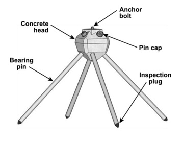
Pin Piers- Approved for use as long as installed per manufacturers installation instructions. Caps must be left off to measure pins at time of inspection. Must include the type and size of the pin pier. Pin piers have limited load capacity.
Helical Piers- Must be engineered and installed by licensed installers. Must provide preliminary design for plan review and have an installation report available at final inspection showing achieved torques and bearing capacity for each pier.

Decking Materials
Wood materials shall be No. 2 grade or better lumber, preservative-treated in accordance with Section R317, or approved, naturally durable lumber. Plastic composite exterior deck boards, stair treads, guards and handrails shall comply with the requirements of ASTM D7032. Provide Manufacturers current code compliance research report (CCRR) and tagged material.
Ledger boards
Deck ledgers shall be a minimum 2-inch by 8-inch nominal, pressure-preservative-treated Southern Pine, incised pressure-preservative-treated hem-fir, or approved, naturally durable, No. 2 grade or better lumber. Deck ledgers shall not support concentrated loads from beams or girders. Deck ledgers shall not be supported on stone or masonry veneer.
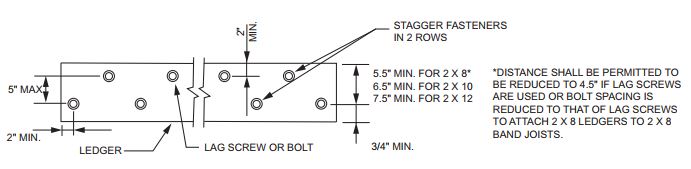
- Fastening: Fasteners used in deck ledger connections in accordance with Table R507.9.1.3(1) shall be hot-dipped galvanized, stainless steel or connectors approved for ledger board connection. Ledger boards must be installed in accordance with Figure R507.9.1.3(1). Alternative fasters must be installed per manufacturer installation instructions.
TABLE R507.9.1.3(1) DECK LEDGER CONNECTION TO BAND JOIST
| Connection Details | Joist Spana | ||||||
| 6' and less | 6'1" -8' | 8'1"-10' | 10'1"-12' | 12'1"-14' | 14'1"-16' | 16'1"-18' | |
| On-Center spacing of fasteners | |||||||
| 1/2-inch diameter lag screw with 1/2-inch maximum sheathingb,c | 30 | 23 | 18 | 15 | 13 | 11 | 10 |
| 1/2-inch diameter bolt with 1/2-inch maximum sheathingc | 36 | 36 | 34 | 29 | 24 | 21 | 19 |
| 1/2-inch diameter bolt with 1-inch maximum sheathingd | 36 | 36 | 29 | 24 | 21 | 18 | 16 |
For SI: 1 inch=25.4 mm, 1 foot= 304.8 mm, 1 pound per square foot = 0.0479 kPa.
- Ledgers shall be flashed in accordance with Section R703.4 to prevent water from contacting the house band joist.
- The tip of the lag screw shall fully extend beyond the inside face of the band joist.
- Sheathing shall be wood structural panel or solid sawn lumber.
- Sheathing shall be permitted to be wood structural panel, gypsum board, fiberboard, lumber or foam sheathing. Up to 1/2-inch thickness of stacked washers shall be permitted to substitute for up to 1/2" of allowable sheathing thickness where combined with wood structural panel or lumber sheathing.
DECKS CANNOT BE SUPPORTED BY CANTILEVERS extending from the primary structure, or from another deck. Exceptions are granted only if proof is provided of the capability of the cantilevers to give adequate support.
Flashing
All penetrations to the exterior finish of the house shall be flashed and sealed to be made waterproof.
Beams
Maximum allowable spans for wood deck beams shall be in accordance Table R507.5. Beam plies shall be fastened with two rows of 10d (3-inch x 0.128-inch) nails minimum at 16 inches on center along each edge. Beams shall be permitted to cantilever at each end up to one-fourth of the allowable beam span. Deck beams of other materials shall be permitted where designed in accordance with accepted engineering practices.
Table R507.5 Deck Beam Span Lengths
| Species No. 2 grade or better | Size | Deck Joist Span Less Than or Equal to: | ||||||
| 6' | 8' | 10' | 12' | 14' | 16' | 18' | ||
| Ft-in | Ft-in | Ft-in | Ft-in | Ft-in | Ft-in | Ft-in | ||
| Southern Pine | (2) 2x6 | 6-11 | 5-11 | 5-4 | 4-10 | 4-6 | 4-3 | 4-0 |
| (2) 2x8 | 8-9 | 7-7 | 6-9 | 6-2 | 5-9 | 5-4 | 5-0 | |
| (2) 2x10 | 10-4 | 9-0 | 8-0 | 7-4 | 6-9 | 6-4 | 6-0 | |
| (2) 2x12 | 12-2 | 10-7 | 9-5 | 8-7 | 8-0 | 7-6 | 7-0 | |
| (3) 2x6 | 8-2 | 7-5 | 6-8 | 6-1 | 5-8 | 5-3 | 5-0 | |
| (3) 2x8 | 10-10 | 9-6 | 8-6 | 7-9 | 7-2 | 6-8 | 6-4 | |
| (3) 2x10 | 13-0 | 11-3 | 10-0 | 9-2 | 8-6 | 7-11 | 7-6 | |
| (3) 2x12 | 15-3 | 13-3 | 11-10 | 10-9 | 10-0 | 9-4 | 8-10 | |
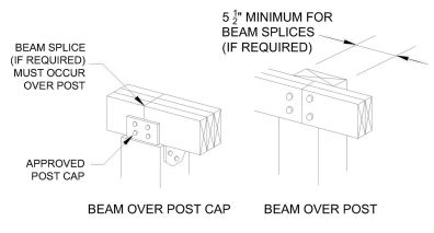
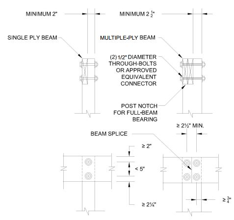
Beam and bearing connection: The ends of beams shall have not less than 1 ½ inches of bearing on wood or metal and not less than 3 inches of bearing on concrete or masonry for the entire width of the beam. Where multiple-span beams bear on intermediate posts, each ply must have full bearing on the post in accordance with Figures R507.5.1(1) and R507.5.1(2).
Joists
Maximum allowable spans for wood deck joists shall be in accordance with Table R507.6. The maximum joist spacing shall be limited by the decking materials. The maximum joist cantilever shall be limited to on-fourth of the joist span, or the maximum cantilever length specified in Table R507.6, whichever is less.
Table R507.7 Maximum Joist Spacing for Decking
| Decking Material Type and Nominal Size | Maximum On-Center Joist Spacing | |
| Decking perpendicular to joist | Decking diagonal to joist | |
| 5/4-inch decking | 16 inches | 12 inches |
| 2-inch decking | 24 inches | 16 inches |
| Plastic composite | Comply with ASTM D7032 | Comply with ASTM D7032 |
Table R507.6 Deck Joist Spans (ft.-in. Typical Deck Joist Spans)
| Species #2 Grade | Size | Allowable Joist Span | Maximum Cantilever | ||||
| Spacing of Deck Joists | Spacing of Deck Joists with Cantilevers | ||||||
| 12" | 16" | 24" | 12" | 16" | 24" | ||
| Southern Pine | 2x6 | 9-11 | 9-0 | 7-7 | 1-3 | 1-4 | 1-6 |
| 2x8 | 13-1 | 11-10 | 9-8 | 2-1 | 2-3 | 2-5 | |
| 2x10 | 16-2 | 14-0 | 11-5 | 3-4 | 3-6 | 2-10 | |
| 2x12 | 18-0 | 16-6 | 13-6 | 4-6 | 4-2 | 3-4 | |
Lateral Connections
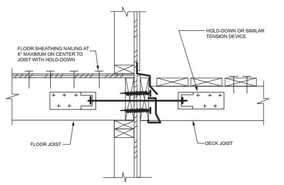
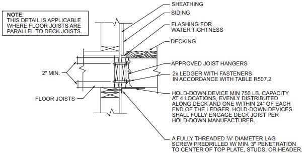
Lateral loads shall be transferred to the ground or to a structure capable of transmitting them to the ground. Where the lateral load connection is provided in accordance with Figure 507.9.2(1), hold-down tension devices shall be installed in not less than two locations per deck, within 24-inches of each end of the deck. Each device shall have an allowable stress design capacity of not less than 1,500 pounds. Where the lateral load connections are provided in accordance with Figure R507.9.2(2), the hold-down tension devices shall be installed in not less than four locations per deck, and each device shall have an allowable stress design capacity of not less than 750 pounds.
Joist hangers
- Joists framing into the side of a wood beam or house ledger shall be supported by joist hangers.
- Only approved fasteners may be used in joist hangers with all holes filled.
- Galvanized common nails, 2 ½” minimum lengths shall be used in double shear nail holes.
- Double and Triple hangers are required on Double and Triple members, respectively.
- DO NOT MODIFY HANGERS. Use concealed flange hangers at the ends of the ledger.
- ANGLE BRACKETS ARE PROHIBITED, unless approved for use by manufacturer.
Double Sheer Hanger

Concealed Flange Hanger

Lighting
All exterior stairways shall be provided with a means to illuminate stair landings and treads. An artificial light source located in the direct vicinity of the top landing of the stairway is required. As an alternate, a light source may be provided directly over each stairway section.
Guardrails
All decks 30 inches or more above grade must have a guardrail at least 36 inches in height and intermediate rail spacing or pattern so that a 4-inch sphere cannot pass through. Guardrails must withstand a 200-pound lateral force.
Stairways
A stairway with 4 or more risers and less than 30 inches above grade requires a handrail on one side only. Stairways that are more than 30 inches above grade must have a guardrail on both sides and at least one handrail. The guardrails shall have an intermediate rail spacing or pattern so that a 4-inch sphere cannot pass through.
The handgrip portion of the handrail shall be placed between 34-38 inches measured from the nosing of the stair treads. The handrail shall not be less than 1 ¼ -2 inches in cross section and shall be continuous from a point directly above the top riser to a point directly above the lowest riser of the flight dimension. All handrails shall return or terminate to the newel post or safety terminals.
The height of the risers can be between 4 -7 ¾ inches. The height between the smallest riser and the tallest riser cannot exceed 3/8 inch. The minimum tread depth is 10 inches.
All stairways shall be a minimum width of 36 inches.
A solid pad must support stair stringers located at grade.
There shall be a landing at the top and bottom of each stairway. The landing shall not be smaller than the width of the stairway and shall extend not less than 36 inches in the direction of travel.
- Decks 30” or more above grade require a guard rail not less than 36” measured from the deck surface.
- Guards on the side of the stairs shall not be less than 34” measured vertically from a line connecting the leading edge of the treads. Where the guard also serves as a handrail, it shall not be more than 38”. The clear width of a stairway between guards and/or newel posts shall not be less than 36”.
- Openings in the guard shall not allow the passage of a 4” diameter sphere.
- The triangle formed by the riser, tread, and the bottom rail shall not allow the passage of a 6” diameter sphere.
- The minimum depth tread shall be 10”. The greatest depth shall not exceed the smallest by more than 3/8”.
- The height of the risers can be between 4 inches and 7 ¾ inches. The greatest height shall not exceed the smallest by more than 3/8”. Open risers shall not allow a 4” sphere to pass through.
- Stair stringers shall be attached by metal straps, hangers, and/or structural screws.
- A nosing of not less than ¾” or more than 1 ¼” shall be provided on stairways.
- There shall be a landing at the top and bottom of a stairway not less than the width of the stairs and 36” in the direction of travel.
- Decks more than 30” above grade require a guard.
Building Safety
Phone: 651-480-2342
Sign up to our News and Notices
Stay up to date on the city's activities, events, programs and operations by subscribing to our news, notices and publications.